
Building a Notebook with AI and a 3D Printer
I've been using AI for various things, including writing software for MooBudget, experimenting with music production, and making an automated Jotepad tutorial. This time, I wanted to try using it to design something I could print and hold.
I wanted a refillable notebook. I had ordinary A4 printer paper, a 3D printer, and PETG filament. I didn't have a paper cutter, so folding the paper in half seemed like a reasonable place to start.
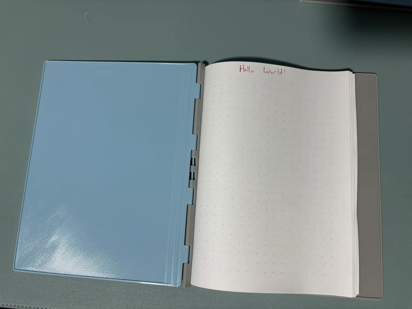
Hello world! My printed notebook with dot paper I printed on A4 sheets and folded to A5.
I'm not an industrial designer. But I could describe what I wanted, look at a model, and try a printed part. I wanted to see how far that could take me with AI helping to generate the designs.
The process became familiar quite quickly: describe a requirement, review an implementation, test something small, report a problem, and revise. There was scope creep, debugging, and eventually a decision to cut features. Very much like a software project, except the feedback sometimes involved a piece of plastic that wouldn't fit or had deformed in my hand.
The latest design is labelled V26. That doesn't mean I printed 26 complete notebooks. Many revisions were models, small tests, or changes to a single part. The interesting bits happened when something I could hold contradicted what looked convincing on screen.
The photos show my physical prints. CAD previews and diagrams are labelled separately in their captions.
Start with folded paper
The first proposal used two printed covers, a spine, tape hinges, and elastic loops holding folded paper. It was enough to make the idea concrete, and enough for me to realise that I didn't want tape.
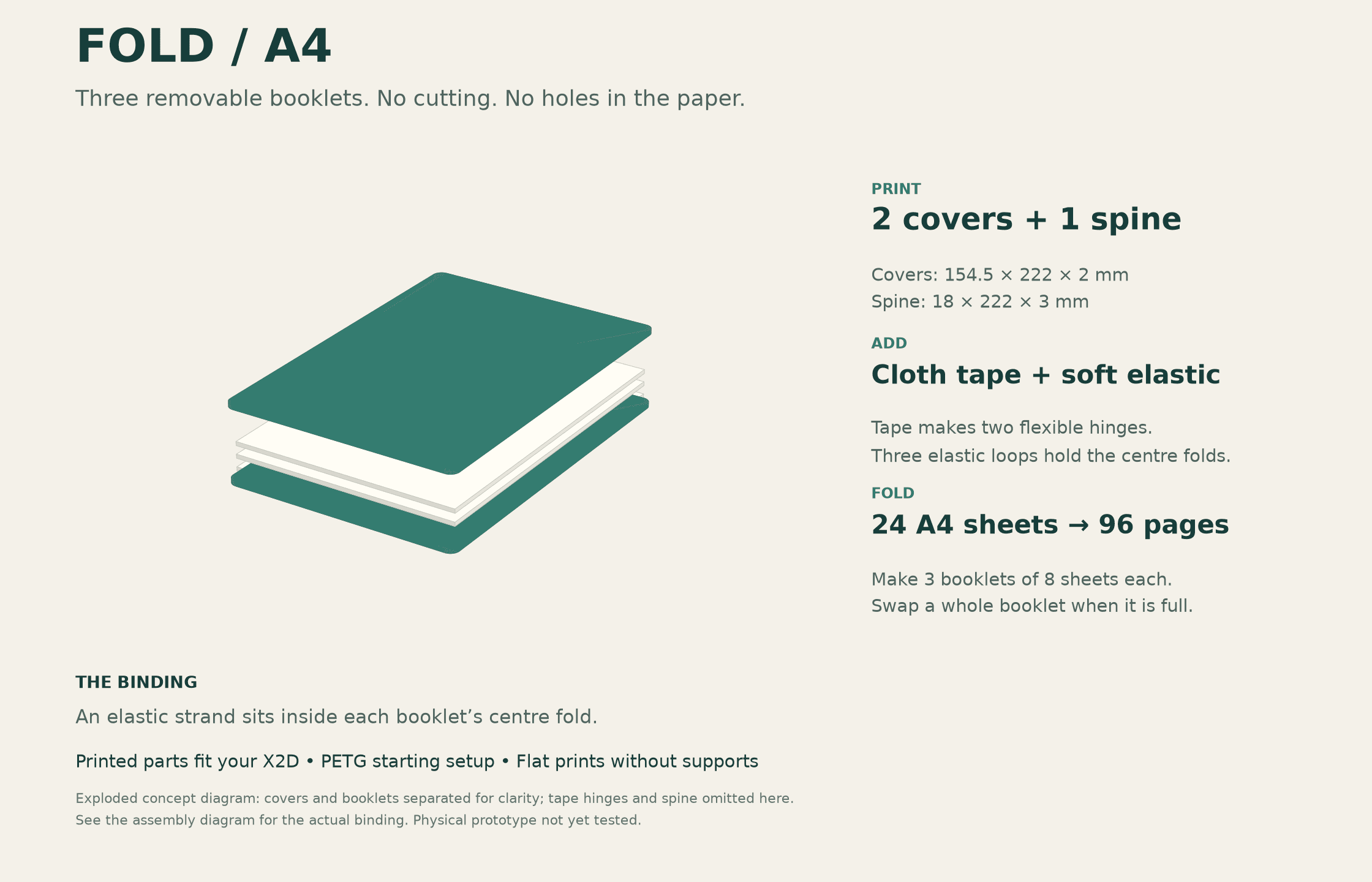
CAD concept diagram. I rejected the tape hinges before printing this version; the paper capacity also changed later.
Printed hinges replaced the tape. An early paper target was about 15 folded A4 sheets, giving 30 leaves or 60 writable sides. I wanted simple assembly, preferably without screws, and a notebook that felt like a normal book.
Those requirements emerged gradually. Being shown a model helped me decide what mattered: where a knot would sit, whether a fitting would protrude, and whether the cover would be comfortable to write on. I didn't have a complete specification ready at the beginning.
For the modelling, I used GPT-6 Astra with medium reasoning and fast mode. The actual modelling happened through code. Early designs included OpenSCAD sources; later revisions used Python geometry scripts to export printable parts and viewing assemblies. I could request a change in ordinary language, then inspect the resulting geometry. That made the experiment accessible, while still leaving plenty for me to evaluate.
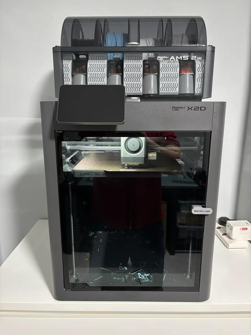
I had a Printrbot Simple Metal about ten years ago. Coming back to home 3D printing with the X2D, I've found the whole process much easier. That makes it much more approachable to try an idea, print a small part, and revise it.
Then I added a pen. And stencils.
A notebook should probably hold a pen. I also wanted somewhere to keep thin tracing templates for tables and shapes. Each addition sounded small on its own.
The pen moved inside, across the top, and eventually outside. Stencils led to removable clips, sliding sockets, retaining rails, and clearance for fingers. Keeping raised fittings away from the writing surface contributed to a thicker cover. At one stage, the design had 245 mm-tall covers with 6 mm-thick panels.
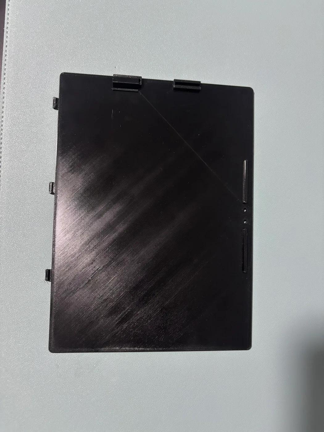
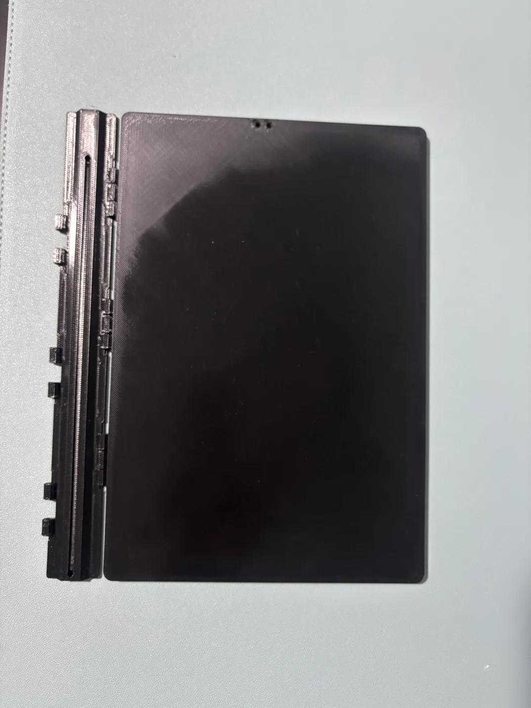
Physical prints from the earlier designs: a cover with accessory mounts and stops, and a cover beside its spine.
All of these choices had a reason. Together, they made the object bigger. When I printed a back piece, my reaction was that it looked quite large.
That was a useful review. A dimension on screen hadn't given me the same sense of proportion as holding the printed cover. I could keep rearranging the accessories, but I also needed to reconsider how much notebook I wanted around my paper.
Printing made vague requirements precise
The pen holder exposed an early measurement mistake. I had described the pen as roughly 14 mm across, but that included its pocket clip. The barrel itself was about 10.5 mm. A grip designed around the larger measurement was too big.
Once corrected, the new grip fitted well and felt sturdy. That gave us a successful part to preserve while working on its connection to the cover.
The stencil holder had a different problem: its small supported geometry printed poorly, and I couldn't properly remove the supports. I asked for a simpler side profile that could print on its side without them. That changed the design around the way it would be manufactured.
Then came retention. A connector could fit into its socket and still fall out when tilted. We tried small friction-fit variants and settled on the snug one. These little tests were useful because I could adjust the interface without printing an entire cover each time.
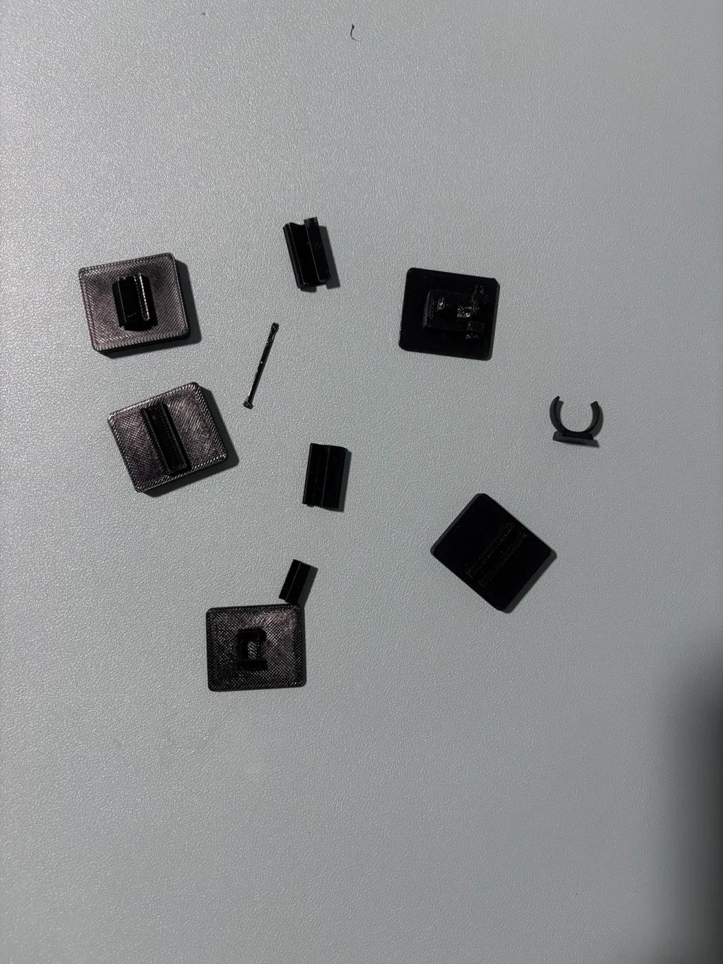
Physical prints: small mounts, connectors, a pin, and a pen clip from the experiments. These let me inspect individual interfaces before committing to larger pieces.
But fitting into the socket was only part of the job. The stencil clip stopped at the socket border and couldn't reach the sheet it was supposed to hold. I had to ask for the two parts to be assessed together.
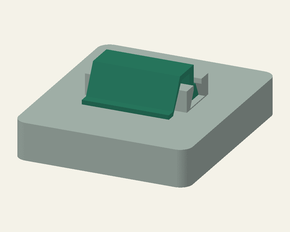
CAD preview: the revised clip and socket viewed together. The longer arm addressed a reach problem that inspecting the parts separately had missed.
As a software developer, I recognised this one. Two components can look fine individually while their interaction is wrong. Here, the integration bug was visible in plastic.
There were also tradeoffs that a fit check couldn't settle. Stronger clips became too tight. Repeatedly lifting one from its lip caused deformation. A longer nose made insertion easier but encroached on the paper area. I accepted less reach to preserve that clearance.
“Hold a stencil” had turned into several separate questions: could I insert it, would it stay, could I remove it comfortably, and would the clip survive repeated use?
The most useful revision removed features
Eventually, I said I was reducing the MVP scope.
I removed the clip system and the tall area that accommodated the fittings. Instead, a low rim around the back cover would help keep a stencil from sliding sideways. The covers shortened to 218 mm, much closer to the folded paper's 210 mm height.
The idea was to put the stencils inside and wrap a band sideways around the closed book. The band would press the covers and contents together, holding the stencils in place, while the raised perimeter ridge would stop them from slipping out at the edges. I also figured the pen could simply tuck under one of the covers and be held by that same pressure. This gave me a much simpler way to approach storage, with retention still something to check in use.
I also made the front and back the same part, printed twice. The notebook was down to three main printed pieces: two identical covers and one spine. As I printed more, I wanted to be able to mix and match covers and spines easily, without keeping separate front and back designs. That meant the filament holding the hinges together needed to be removable, so I could take the book apart and swap its parts around.
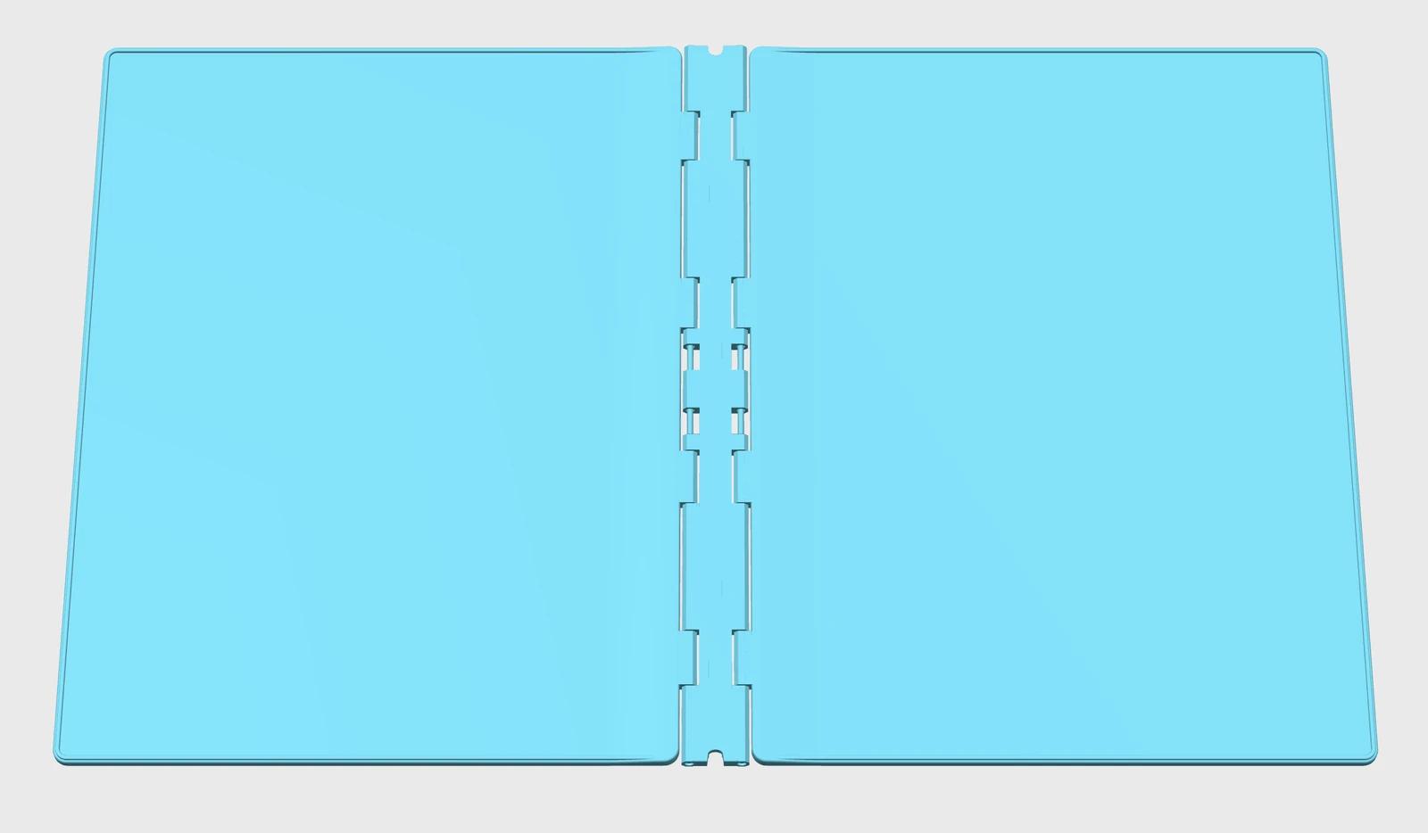
3MF assembly opened in Bambu Studio: two matching rimmed covers and a spine, shown flat. This is a model view, not a print layout.
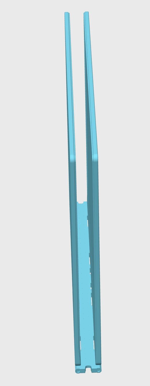
The folded assembly viewed from the end in Bambu Studio, with the space between the covers visible before adding paper.
This was one of the clearest product decisions in the project. AI made it easy to ask for another variant. I still had to decide when a feature wasn't worth carrying forward.
Small tests helped, until the full assembly disagreed
The hinges evolved too. We moved from individual printed pins to lengths of filament threaded through matching cover and spine tunnels.
Feeding filament through a long tunnel proved difficult. Splitting insertion between the top and bottom reduced the distance each strand needed to travel, with a stop in the middle. The nominal holes grew from 2.1 mm to 2.2 mm, and later to 2.4 mm.
I asked for cheap hinge samples before committing to full parts. A half-height test kept one strand's full insertion path while using less material. At one point, a print went well and the filament stayed in place.
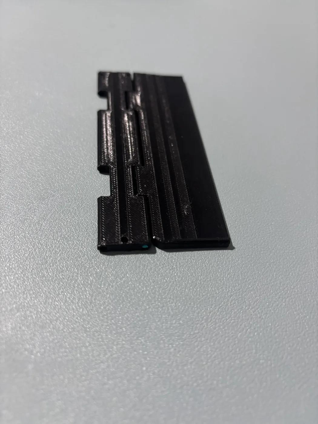
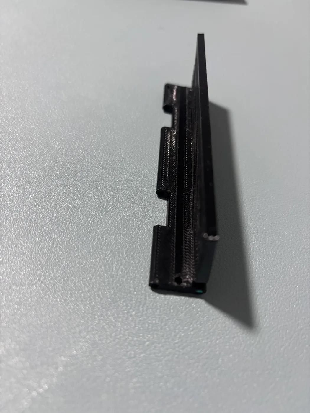
Physical test sample shown flat and raised. The little blue dot at the end is the inserted filament. A narrow strip let me try the hinge without printing a whole cover.
But the small tests didn't tell the whole story. When I printed the full assembly, some paths jammed at the entrance and others farther along. Some holes worked while others didn't. We discussed local roughness, tunnel roofs, and alignment, but didn't establish a measured cause.
Unfolded paper clips worked as an alternative, although they could slide outward during movement. The new 2.4 mm spine seemed to work well, and I preferred the closer fit of filament.
It was a useful limit to discover: a small sample could check feeding through that sample. It couldn't establish that the entire print would behave the same way.
I also had to question a digital paper-clearance check. The first diagram placed a paper rectangle on the cover. I asked whether it accounted for the paper attached at the spine. The revised analysis considered the fold and the open and closed positions. That answered a better question, although it still couldn't tell me how actual pages would turn under elastic tension.
Making it easy to take apart introduced a weak point
Once filament was working as a hinge pin, I needed a practical way to pull it out again. Being able to mix and match the covers and spine depended on that. Access cutouts near the ends gave me somewhere to grip the filament with pliers.
Then I did a drop test. The weak areas were the ends where we'd added those cutouts.
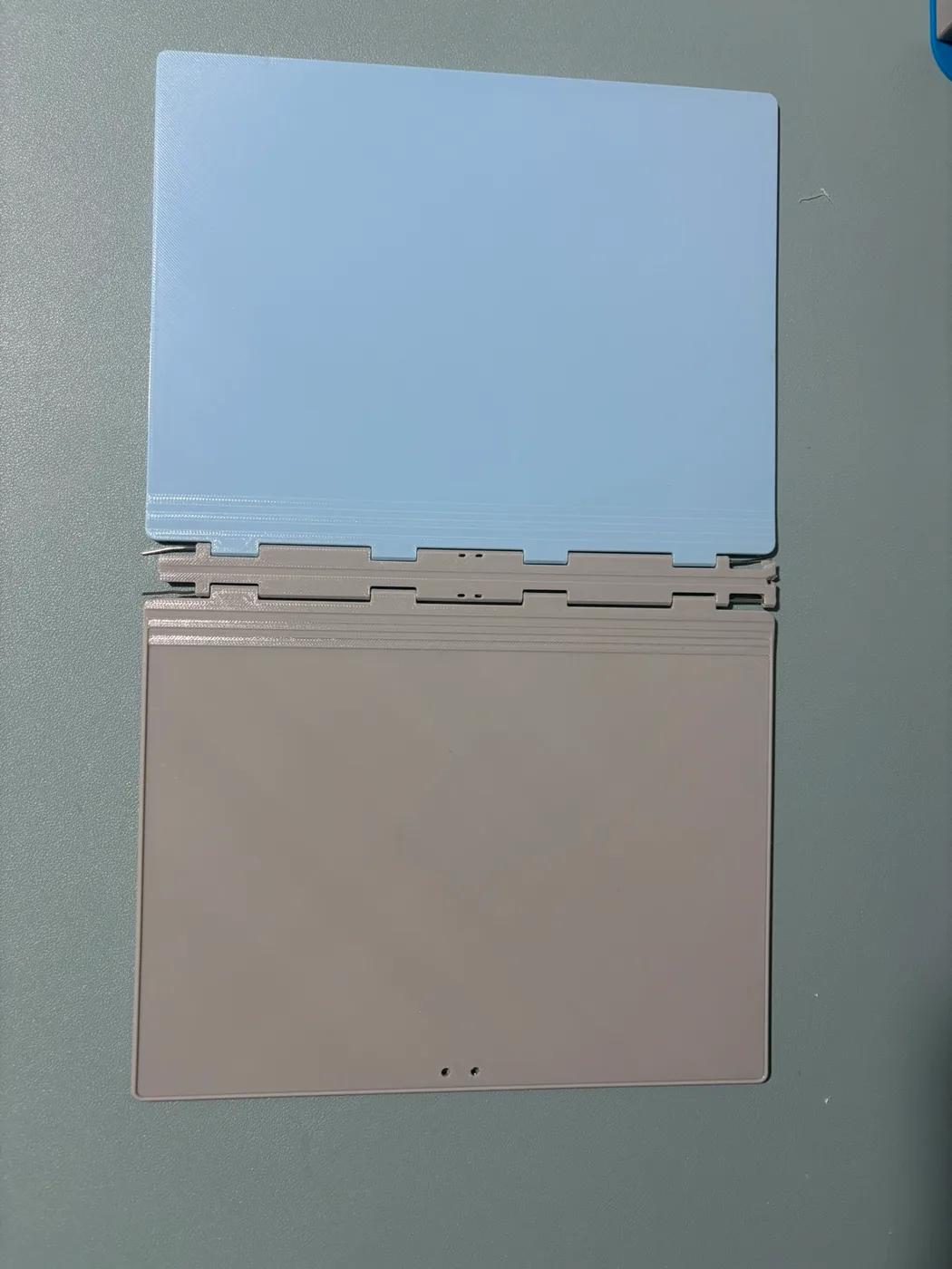
The assembly where filament would not fit, so I used paper clips instead. This is also the one I drop-tested: the broken parts are visible on the right, with the surviving thin ends of the spine on the left.
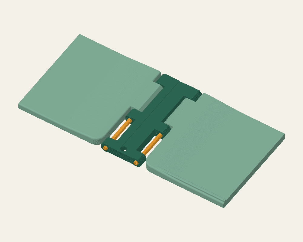
CAD preview of an earlier end-access design. My drop test exposed weakness in this design family around the end cutouts.
The next change restored the end tunnels and moved access toward the centre, leaving enclosed pockets for the filament tips. Subsequent revisions adjusted how much tunnel remained on either side of each opening.
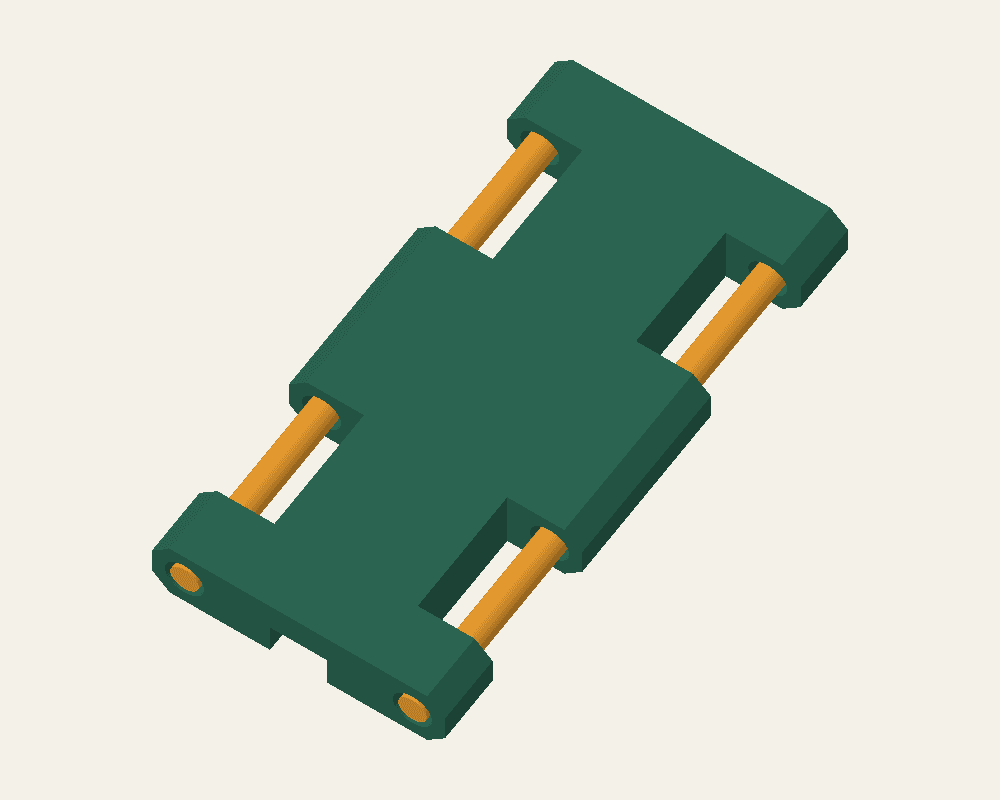
CAD preview of V26's central access arrangement. It retains equal 4.75 mm tunnel sections beside each 8 mm opening; physical testing of this revision is still pending.
This was a direct consequence of testing something beyond assembly. Making the filament accessible had removed material from a place that turned out to be vulnerable. The revised geometry responds to that observation, but I haven't yet established that V26 survives another drop.
Where the notebook stands
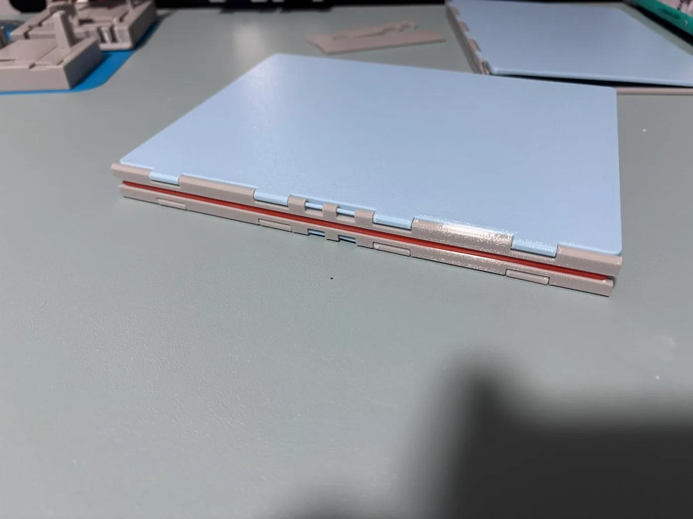
Physical print: the notebook assembled, with the binding band running along the spine.
I now use 20 sheets of A4 paper with a dot grid I printed myself. Folded to A5 and added to the notebook, the paper is held steadily by the binding rubber band. That gives me 40 leaves, or 80 writable sides.
The current design uses two identical rimmed covers, a spine, four filament strands for the hinges, and a rubber band to bind the folded paper. A separate band wraps sideways around the closed book, providing the pressure intended to hold the stencils and a tucked-in pen. The perimeter ridges help contain the stencils, and removable filament lets me swap covers and spines. The dedicated pen holders and stencil clips are gone.
AI helped me turn an idea into a notebook I can use. Printing and trying the parts showed me what needed changing. There's still more to test, but for now, I'm happy to have somewhere to write.